
OSPF Configuration - Introduction
OSPF is an Interior Gateway Protocol (IGP) developed by the OSPF working group of the Internet Engineering Task Force (IETF). OSPF is a non-proprietary interior gateway protocol (IGP) that overcomes the deficiencies of other distance vector routing protocols and distributes routing information within a single OSPF routing domain. OSPF introduced concepts of variable-length subnet mask (VLSM), which supports classless routing, summarization, authentication, and external route tagging, and IPv6 support in OSPFv3.
OSPF advertises link-state advertisements (LSAs) that contain the link state and link metric to create neighboring routers. Received LSAs are stored in a local database called the link-state database (LSDB) and advertise the link-state information to neighboring routers exactly as the original advertising router advertised it. This process floods the LSA throughout the OSPF routing domain just as the advertising router advertised it. All OSPF routers maintain a synchronized identical copy of the LSDB. The LSDB provides the topology of the network, in essence providing the router a complete map of the network. All OSPF routers run the Dijkstra Shortest Path First (SPF) algorithm to construct a loop-free topology of shortest paths.
OSPF provides scalability for the routing table by using multiple OSPF areas within the routing domain. OSPF uses a two-tier hierarchical architecture, where Area 0 is known as the backbone and all other areas must connect to Area 0. In other words, Area 0 provides transit connectivity between nonbackbone areas. Nonbackbone areas advertise routes into the backbone, and the backbone then advertises routes into other nonback areas.
Network Topology
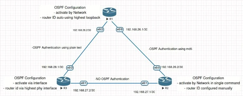
Configure Router ID
The OSPF router ID (RID) is a 32-bit number that uniquely identifies an OSPF router. IOS nodes use the highest IP address of the any up loopback interfaces. If there are no up loopback interfaces, the highest IP address of any active up physical interfaces becomes the RID when the OSPF process initializes.
****
**Auto assigned Router ID **
Current Configuration
There is no any configuration that defining the Router ID for OSPF, but there is IP Address of Loopback interface.
router ospf 26
log-adjacency-changes
network 192.168.26.0 0.0.0.255 area 0
network 192.168.28.0 0.0.0.255 area 0

ROUTER1#show ip interface brief
Interface IP-Address OK? Method Status Protocol
Ethernet0/0 192.168.26.1 YES manual up up
Ethernet0/1 unassigned YES unset administratively down down
Ethernet0/2 192.168.28.2 YES manual up up
Ethernet0/3 unassigned YES unset administratively down down
Loopback0 1.1.1.1 YES manual up up

ROUTER1#
Result
Because IP Address of Loopback is configured, than its using as Router ID
ROUTER1#show ip ospf
Routing Process "ospf 26" with ID 1.1.1.1
Start time: 00:12:07.772, Time elapsed: 01:13:24.280
Configuration
Because there is no any IP Address of loopback interface is UP, the Router ID automatically assigned by Highest IP Address.
router ospf 22
log-adjacency-changes

ROUTER3#show ip int br
Interface IP-Address OK? Method Status Protocol
Ethernet0/0 unassigned YES unset administratively down down
Ethernet0/1 192.168.27.2 YES manual up up
Ethernet0/2 192.168.28.1 YES manual up up
Ethernet0/3 unassigned YES unset administratively down down

ROUTER3#
Result
Highest IP Address of physical interface is used as Router ID.
ROUTER3#show ip ospf
Routing Process "ospf 22" with ID 192.168.28.1
Start time: 00:18:05.908, Time elapsed: 01:11:09.684
Router ID Configured manually
Configuration
Based on configuration as below, we can see the Router ID is manually configured using 2.2.2.2
router ospf 22
router-id 2.2.2.2
log-adjacency-changes
network 0.0.0.0 255.255.255.255 area 0
Result
Same as cofniguration, Router ID that used same as configuration 2.2.2.2 eventhought IP Loopback is configured.
ROUTER2#show ip ospf
Routing Process "ospf 22" with ID 2.2.2.2
Start time: 00:33:31.916, Time elapsed: 00:53:28.504
Activate Routing OSPF
At CISCO IOS most of the configuration resides under the OSPF process, but some OSPF options go directly on the interface configuration submode. IOS routers can enable OSPF on an interface with a network statement or by associating an OSPF process under the interface. A common misconception is that the network statement advertises the networks into OSPF; in reality, though, the network statement is enabling OSPF on the interface. The interface is then advertised in OSPF through the LSA. The network statement uses a wildcard mask, which allows the configuration to be as specific or vague as necessary.
OSPF Configuration with Explicit Subnet
Configuration
- Entering configuration mode
- Entering routing ospf configuration
- Define OSPF Process ID
- Define subnet, wildcard mask, and area id
router ospf 26
log-adjacency-changes
network 192.168.26.0 0.0.0.255 area 0
network 192.168.28.0 0.0.0.255 area 0
Result
ROUTER1#show ip ospf interface brief
Interface PID Area IP Address/Mask Cost State Nbrs F/C
Et0/2 26 0 192.168.28.2/30 10 BDR 1/1
Et0/0 26 0 192.168.26.1/30 10 BDR 1/1

ROUTER1#show ip ospf neighbor
Neighbor ID Pri State Dead Time Address Interface
192.168.28.1 1 FULL/DR 00:00:32 192.168.28.1 Ethernet0/2
2.2.2.2 1 FULL/DR 00:00:34 192.168.26.2 Ethernet0/0
OSPF Configuration for All Interfaces
Configuration
- Entering configuration mode
- Entering routing ospf configuration
- Define OSPF Process ID
- Define subnet, wildcard mask, and area id
router ospf 22
router-id 2.2.2.2
log-adjacency-changes
network 0.0.0.0 255.255.255.255 area 0
Result
ROUTER2#sh ip ospf interface brief
Interface PID Area IP Address/Mask Cost State Nbrs F/C
Et0/1 22 0 192.168.27.1/30 10 BDR 1/1
Et0/0 22 0 192.168.26.2/30 10 DR 1/1

ROUTER2#sh ip ospf neighbor
Neighbor ID Pri State Dead Time Address Interface
192.168.28.1 1 FULL/DR 00:00:33 192.168.27.2 Ethernet0/1
1.1.1.1 1 FULL/BDR 00:00:39 192.168.26.1 Ethernet0/0

ROUTER2#
OSPF Configuration on IOS for Specific Interface
Configuration
- Entering configuration mode
- Entering interface configuration
- define ospf process id and area
router ospf 22
log-adjacency-changes

ROUTER3#show running-config interface ethernet 0/2
!
interface Ethernet0/2
ip address 192.168.28.1 255.255.255.252
ip ospf 22 area 0
end

ROUTER3#show running-config interface ethernet 0/1
!
interface Ethernet0/1
ip address 192.168.27.2 255.255.255.252
ip ospf 22 area 0
end
Forming OSPF Adjacency
In order to create adjacency between two Router, there are several parameters that need to be matched. the details as follows
Authentication type and credentials (if any)
OSPF supports two types authentication:
- Plain text: Provides little security, as anyone with access to the link can see the password with a network sniffer
- MD5 cryptographic hash: Uses a hash instead, so the password is never sent out the wire, and this technique is widely accepted as being th260 e more secure mode
Configuration
Authentication that are used by Router 2 and Router 1 is not same. Router 2 using md5 with key-index is 1, and Router 1 using plain text authentication key which is “cisco”.
ROUTER2#sh running-config interface ethernet 0/0
interface Ethernet0/0
ip address 192.168.26.2 255.255.255.252
ip ospf authentication message-digest
ip ospf message-digest-key 1 md5 cisco
end

ROUTER1#show running-config interface ethernet 0/0
interface Ethernet0/0
ip address 192.168.26.1 255.255.255.252
ip ospf authentication-key cisco
end
Result
No adjacency toward ROUTER2 from ROUTER1, because the authentication is not match.
ROUTER1#show ip ospf neighbor
Neighbor ID Pri State Dead Time Address Interface
192.168.28.1 1 FULL/DR 00:00:37 192.168.28.1 Ethernet0/2
ROUTER1#
To establish the link, we need to re-configure authentication key and authentication mode are same for both link
ROUTER2#sh running-config interface ethernet 0/0
interface Ethernet0/0
ip address 192.168.26.2 255.255.255.252
ip ospf authentication message-digest
ip ospf message-digest-key 1 md5 cisco
end

ROUTER1#show running-config interface ethernet 0/0
interface Ethernet0/0
ip address 192.168.26.1 255.255.255.252
ip ospf authentication message-digest
ip ospf message-digest-key 1 md5 cisco
end
Result
Adjacency toward ROUTER2 and ROUTER3 from ROUTER1 are established
ROUTER1#show ip ospf neighbor
Neighbor ID Pri State Dead Time Address Interface
192.168.28.1 1 FULL/DR 00:00:35 192.168.28.1 Ethernet0/2
2.2.2.2 1 FULL/DR 00:00:31 192.168.26.2 Ethernet0/0
ROUTER1#
Area ID
OSPF areas are a logical grouping of routers, or more specifically a logical grouping of router interfaces. Area membership is set at the interface level and the area ID is included in the OSPF Hello packet. An interface can only belong to one area.
Configuration
ROUTER 1 using area 0, but ROUTER 3 using area 3, Area ID should be same
for both link to establish OSPF Ajacacency.
ROUTER 1
router ospf 22
router-id 2.2.2.2
log-adjacency-changes
network 0.0.0.0 255.255.255.255 area 0
ROUTER3
interface Ethernet0/1
ip address 192.168.27.2 255.255.255.252
ip ospf 22 area 3
end
Result
Adjacency to Router3 is missing, because the area id is not match for both link.
Neighbor ID Pri State Dead Time Address Interface
1.1.1.1 1 FULL/BDR 00:00:39 192.168.26.1 Ethernet0/0
ROUTER2#
and also there is log as below that indicate the mismatch area id*
*
*Oct 26 17:17:41.551: %OSPF-4-ERRRCV: Received invalid packet: mismatch area ID, from backbone area must be virtual-link but not found from 192.168.27.1, Ethernet0/1
To establish the link, we need to re-configure area id is same for both link
router ospf 22
router-id 2.2.2.2
log-adjacency-changes
network 0.0.0.0 255.255.255.255 area 0

interface Ethernet0/1
ip address 192.168.27.2 255.255.255.252
ip ospf 22 area 0
end
Result
After Area ID is match for both links, adjacency to ROUTER3 is established
*Oct 26 17:21:26.079: %OSPF-5-ADJCHG: Process 22, Nbr 2.2.2.2 on Ethernet0/1 from LOADING to FULL, Loading Done

ROUTER2#show ip ospf neighbor
Neighbor ID Pri State Dead Time Address Interface
192.168.28.1 1 FULL/BDR 00:00:35 192.168.27.2 Ethernet0/1
1.1.1.1 1 FULL/BDR 00:00:34 192.168.26.1 Ethernet0/0
ROUTER2#
OSPF hello and dead timers
OSPF Hello packets are responsible for discovering and maintaining neighbours. In most instances, the router sends Hello packets to the AllSPFRouters address (224.0.0.5). Dead Interval is time span for router to wait to hear a Hello from neighbour router before it declares that router is down. Dead Interval is four times the hello timer.
The default OSPF hello timer interval varies based on the OSPF network type. OSPF allows modification to the hello timer interval with values between 1 and 65,535 seconds. Changing the hello timer interval modifies the default dead interval, too. Hello and dead interval timers must match for OSPF Neighbors to become adjacent.
Configuration
Router 2 using hello timer is 33 seconds, but Router 3 using default timer which is 10 seconds.
ROUTER2#show running-config interface ethernet 0/1
interface Ethernet0/1
ip address 192.168.27.1 255.255.255.252
ip ospf hello-interval 33
end

ROUTER2#show ip ospf interface | i Timer| line
Ethernet0/1 is up, line protocol is up
Timer intervals configured, Hello 33, Dead 132, Wait 132, Retransmit 5

ROUTER3#show running-config interface ethernet 0/1
interface Ethernet0/1
 ip address 192.168.27.2 255.255.255.252
ip ospf 22 area 0
end

ROUTER3#show ip ospf interface | i Timer| line
Ethernet0/1 is up, line protocol is up
Timer intervals configured, Hello 10, Dead 40, Wait 40, Retransmit 5
Result
Because OSPF timer for both link is not matched, OSPF Ajacency will be not established. as we can see OSPF Adjacency to ROUTER3 is missing, and this log is appear
*Oct 26 17:35:19.547: %OSPF-5-ADJCHG: Process 22, Nbr 192.168.28.1 on Ethernet0/1 from FULL to DOWN, Neighbor Down: Dead timer expired

ROUTER2#show ip ospf neighbor
Neighbor ID Pri State Dead Time Address Interface
1.1.1.1 1 FULL/BDR 00:00:33 192.168.26.1 Ethernet0/0

ROUTER2#
To establish the link, the hello time for both Router should be same. Please find below how to configure OSPF Hello timer :
- enter configuration mode
- enter interface that ip ospf hello timer that need to be changed
- define hello timer
ROUTER2#show running-config interface ethernet 0/1
interface Ethernet0/1
ip address 192.168.27.1 255.255.255.252
ip ospf hello-interval 33
end

ROUTER2#show ip ospf interface | i Timer| line
Ethernet0/1 is up, line protocol is up
Timer intervals configured, Hello 33, Dead 132, Wait 132, Retransmit 5

ROUTER3#show running-config interface ethernet 0/1
interface Ethernet0/1
 ip address 192.168.27.2 255.255.255.252
 ip ospf hello-interval 33
 ip ospf 22 area 0
end

ROUTER3#show ip ospf interface | i Timer| line
Ethernet0/1 is up, line protocol is up
Timer intervals configured, Hello 33, Dead 132, Wait 132, Retransmit 5
Result
After Hello timer for both links are same, adjacency to ROUTER3 is established.
ROUTER2#show ip ospf neighbor
Neighbor ID Pri State Dead Time Address Interface
192.168.28.1 1 FULL/DR 00:02:03 192.168.27.2 Ethernet0/1
1.1.1.1 1 FULL/BDR 00:00:34 192.168.26.1 Ethernet0/0

ROUTER2#
RIDs are unique
The OSPF router ID (RID) is a 32-bit number that uniquely identifies an OSPF router. In some OSPF output commands, neighbor ID refers to the RID because the terms are synonymous. The RID must be unique for each OSPF process in an OSPF domain, and must be unique between OSPF processes on a router.
Configuration
Router 2 and Router 3 have same Router ID. This condition should be
avoid, because Router ID should be unique in same OSPF Domain.
ROUTER 2
router ospf 22
router-id 2.2.2.2
log-adjacency-changes
network 0.0.0.0 255.255.255.255 area 0
ROUTER 3
router ospf 22
router-id 2.2.2.2
log-adjacency-changes
Result
NO OSPF Adjacency to ROUTER3 from ROUTER2 because both Router using same Router ID. And there is log as mention duplicate Router ID.
ROUTER2#show ip ospf neighbor
Neighbor ID Pri State Dead Time Address Interface
1.1.1.1 1 FULL/BDR 00:00:38 192.168.26.1 Ethernet0/0

ROUTER2#

*Oct 26 17:50:01.167: %OSPF-4-DUP_RTRID_NBR: OSPF detected duplicate router-id 2.2.2.2 from 192.168.27.2 on interface Ethernet0/1
To establish the link, we need to change the router ID become unique for each Router
router ospf 22
router-id 2.2.2.2
log-adjacency-changes
network 0.0.0.0 255.255.255.255 area 0

router ospf 22
router-id 3.3.3.3
log-adjacency-changes
Result
After Router ID has been changed and all Router have unique Router ID, OSPF Adjacency to ROUTER3 from ROUTER2 is established
ROUTER2#show ip ospf neighbor
Neighbor ID Pri State Dead Time Address Interface
3.3.3.3 1 FULL/BDR 00:02:04 192.168.27.2 Ethernet0/1
1.1.1.1 1 FULL/BDR 00:00:33 192.168.26.1 Ethernet0/0

ROUTER2#
MTU (Maximum Transmission Unit)
Configuration
Router 1 using MTU size is 1000, this condition create un-matched MTU Size.
ROUTER1
interface Ethernet0/0
ip address 192.168.26.1 255.255.255.252
ip mtu 100
ip ospf authentication message-digest
ip ospf authentication-key cisco
ip ospf message-digest-key 1 md5 cisco
end

ROUTER2
interface Ethernet0/0
ip address 192.168.26.2 255.255.255.252
ip ospf authentication message-digest
ip ospf message-digest-key 1 md5 cisco
end
Result
Because that un-match MTU, the status of adjacency to ROUTER2 is EXTART, this is the indication of MTU Missmatched.
ROUTER1#show ip ospf neighbor
Neighbor ID Pri State Dead Time Address Interface
3.3.3.3 1 FULL/DR 00:00:32 192.168.28.1 Ethernet0/2
2.2.2.2 1 EXSTART/DR 00:00:39 192.168.26.2 Ethernet0/0
To establish the link, we need to change the MTU to have same size for each link
- enter configuration mode
- enter interface configuration mode
- change IP MTU size
ROUTER1
interface Ethernet0/0
ip address 192.168.26.1 255.255.255.252
ip mtu 100
ip ospf authentication message-digest
ip ospf authentication-key cisco
ip ospf message-digest-key 1 md5 cisco
end

ROUTER2
interface Ethernet0/0
ip address 192.168.26.2 255.255.255.252
ip mtu 100
ip ospf authentication message-digest
ip ospf message-digest-key 1 md5 cisco
end
Result
Adjacency to ROUTER2 is Established.
ROUTER1#show ip ospf neighbor
Neighbor ID Pri State Dead Time Address Interface
3.3.3.3 1 FULL/DR 00:00:34 192.168.28.1 Ethernet0/2
2.2.2.2 1 FULL/DR 00:00:31 192.168.26.2 Ethernet0/0

ROUTER1#
Summary
Now, we have come to the end of the tutorial. We hope we have helped you to learn how configure OSPF. In order to forming adjacencies between router that using OSPF the parameters that should be matched are Unique Router ID, Authentication Key & Mode, Area ID, OSPF Hello and Dead timer, MTU Size. If you still have any confusion, please let us know in the comment section.